
A Better SVF Preamp
Posted
In another digression from my running series of posts on using Rust to program the Bela, I decided to do some analog audio processing. Why analog instead of the more familiar to me digital signal processing route? There are several reasons, one even related to the aforementioned series!
First, the unrelated reason: I was sorting through some old boxes while looking for something and discovered my long-unused collection of electronics components. Including a set of components that looked a lot like some kind of audio project, forgotten for more than a decade—yes, really, the shipping dates were on the labels! The (expensive) Lundahl LL1538 audio transformer was a good hint, but the slightly yellowed schematic for a Bo Hansén 1975 DI made it clear what it was. So I ordered a PCB from 51xAudio and the handful of missing—probably lost in transport over the course of two moves—components and finally finished the project:

And it worked immediately! With the electronics bug in me revived (the “enthusiasm”-kind not the “programming error”-kind), I got back to thinking about the next project I plan with the Bela—which brings us to the second, Bela-related reason why I'm doing this. Yeah, yeah, “finish the first one first,” I hear you say, but I announced this one right in the second post already! If you don't remember and aren't in the mood to go back to the previous post, here's the TL;DR: I plan to build a polyphonic (bass) guitar using Cycfi Nu modular pickups, using the Bela to perform per-string audio processing.
But wait, isn't that just more digital processing? It is, but a polyphonic setup is a complex beast, typically requiring additional controllers, multiple amplifiers, etc.; and sometimes you just want to plug and play. And to do that, you really want something that behaves like an ordinary, monophonic pickup, which the Nus are not, in multiple ways:
- They are active, i.e., they require a battery.
- They are polyphonic (duh) and therefore output per-string signals instead of a single signal for all strings.
- Internally, the capsules use low-Z, wide-bandwidth pickups.
The first difference isn't much of an issue, and is par for the course for bass guitars, where active pickups and/or active preamps are very common—two of the three I own have a battery compartment. Guitar players are often a little more conservative, but even there, active pickups, such as EMGs or Fishmans, are popular in some genres.
The second difference is easily resolved using a summing amplifier. A summing amplifier is the basis of any active mixer and consists of a single op-amp (operational amplifier) and a handful of resistors—and in most cases some decoupling capacitors to stop any DC offsets from propagating. If you are interested in an overview of how summing amplifiers work and why they are typically better than passive mixers—such as the average multi-pickup bass's balance control—check out Elliot Sound Product's article on audio signal mixing. They generally have a lot of great articles on audio electronics, so definitely worth checking out if you are interested in these things—and I assume you are, having read this far.
The third issue is where things get more complicated. First off, what does low-Z and wide bandwidth even mean in this context? Low-Z is short for low impedance (Z being the standard symbol used for impedances in electronics literature). Essentially, impedance is the frequency-dependent analog to a resistance for AC signals. Typically, a low-Z pickup will have fewer windings and therefore lower DC resistance, lower inductance, and lower winding capacitance than a regular pickup. This leads to a wider bandwidth, i.e., they pick up higher frequencies, typically without losing low-frequency response, and a resonance frequency outside the audible frequency spectrum; but also significantly reduced output, leading to the necessity of active electronics (or transformers in Lace Alumitones).
Wait. Resonance frequency? Yes, all coils, including transformers and pickups, have a resonance frequency, determined by their inductance and winding capacitance—as well as any external loads, such as long cables or a rolled down tone knob. These form a resonant, second-order (12 dB/octave) low-pass filter. The other parasitics of the coil affect the so-called Q of this filter. Q is often described as bandwidth, but that only really applies to second-order band-pass filters. For low-pass filters it makes more sense to think about Q as the gain at the resonant frequency.
Is this resonance desirable? Well, yes and no. In audio transformers for professional audio applications, it is undesirable and a Zobel network is used to tame the resonance and ensure a flat response across the spectrum (check out ESP for details). Guitar pickups are a different story. Here, the resonance is usually smack dab in the middle of the audio spectrum—with resonance frequencies ranging from 800 Hz for humbuckers to 8 kHz for single coils—and a large factor in the perceived “tone” of the pickup. In fact, an amplifier with a low input impedance will lead to significant damping of the resonance leading to a tone that is often described as “dead.” By the way, a DI box as shown above is used convert a high-impedance signal to a balanced low-impedance signal for a microphone preamp when recording. In any case, gitarrenelektronik.de has a number of good articles on guitar pickup resonance and how to affect it (albeit only in German).
So, how can we emulate the response of classic passive pickup with a wide bandwidth active pickup? There are a couple options. One option would be to add a passive RLC-network, optionally with switchable capacitors and resistors, although that would be affected by external loads too, unless an active buffer is added. Another option, the route I chose, is to use an active filter. A great filter topology for this effect is the state variable filter:

While other second-order filter topologies require fewer than three op-amps, the SVF topology allows independent control of frequency and Q. Additionally, both Alembic and Wal, two of the most premium/luxury-level bass builders already use active low-pass filters in their preamps! Presumably, they use SVFs, although it isn't really documented, since their electronics are proprietary. For an overview of active filters for audio, you can, again, check out ESP.
Now let's look into the circuit in more detail! In the schematic above, frequency and Q are set by
and
where is the voltage divider gain
In the literature, variable SVFs are typically dimensioned by replacing the resistors with a dual-gang rheostat (variable resistor) adjustable between 0 Ω and in series with fixed resistors each. Along with the capacitors this sets the frequency range to
Similarly, Q can be controlled by replacing either or by a rheostat in series with a fixed resistor . If is kept fixed and is varied, this results in a Q between
and
I plugged in the numbers for my desired frequency adjustment range of 500 Hz to 10 kHz and Q adjustment range of 0.5 (-6.02 dB) to 5.62 (+15 dB), and the 50 kΩ of the potentiometers—variable voltage dividers that can be wired as rheostats by shorting the wiper to one of the other two pins—resulting in , , , and . Then I got all the necessary parts and set them up on a breadboard.

And it worked. Kind of. While it did what it was supposed to, the adjustment range of the potentiometers was downright terrible, with more than 80% of the adjustment happening in the last 20% or so of the rotation range. Not exactly usable on stage. One method to solve this is to use potentiometers with a different taper. In this case, due to the reciprocal nature of our ranges, it would have to be a reverse audio/inverse logarithmic taper. Hard to source, especially as an individual, and the conformance—how close the resistances of a dual-gang potentiometer are to one another—is generally much worse than for linear potentiometers. And you want them to be close, otherwise the Q will fluctuate while adjusting the frequency.
Luckily, I was recently in contact with Joel de Guzman, principal architect and engineer at Cycfi Research who is designing a custom Nu Multi for me. And he also happens to be a C++ developer like I am—Rust 🦀 is still mostly restricted to hobby work. He suggested using the potentiometers as actual three-terminal potentiometers instead of two-terminal rheostats. So how does that work? Let's figure it out!
To do that, we'll have a look at each of the filter's stages individually. So let's begin with the input / high-pass stage. Here, both the input and the outputs of the other two stages come together as feedback:

So can we just use our potentiometer to completely replace and , since they already form a voltage divider? Well, not really. While the one end of the adjustment range would result in a Q of ⅓ (-9.54 dB), which is far too highly damped to be usable but could potentially work, the other end of the range would result in a Q of… ∞. Not good. So we definitely need resistors at both ends of the potentiometer. But just adding those would result in a similarly ill-suited adjustment range as before, so what can we do? We can fake a non-linear taper by adding a “shaping” resistor in parallel to one of the sides, i.e., between the wiper and one of the two terminals, of the potentiometer as described in an old GeoFex article. In this case, between the wiper and terminal three (the clockwise terminal) of the potentiometer:

To simplify the calculations, let's use resistances relative to , the total resistance of the potentiometer, designated by lowercase . This results in
where is the travel of the potentiometer. By plugging in and as well as and into our voltage divider and Q-equation, we arrive at
and
How do we choose ? I just put tried to plug in a few values, and the optimum appears to be somewhere between and for my desired adjustment range. For other ranges it will be different. If you felt like it, you could even run an optimizer to find the lowest possible error across the entire range. But with , , and for . Obviously, we still have to round these to actually available E series values, but they result in very good adjustment behavior:

The frequency is controlled by the two essentially identical integrator stages. So let's just look at one of them:

What does here is a little less obvious. In the previous case, we had a voltage divider connected to the high-impedance non-inverting input of an op-amp. Here, what we have is just a single resistor connected to the inverting input, which I labeled as virtual ground. What does that mean? Well, op-amps have a very high gain and the negative feedback will try to push the node at the inverting input to as close as the same voltage as is present at the non-inverting input of the op-amp. Which in this case is ground. So instead of a very high-impedance voltage input, we essentially have a very low-impedance current input and controls the current flowing into the node at the inverting input! So what can we do with a potentiometer in this position? We can wire it up as a “current splitter” that controls both how much current flows from the previous stages output and how much of it flows to ground or to virtual ground:

Here is the current flowing out of the previous stage's output and is the current flowing into the virtual ground node. To simplify calculations, let's describe the above circuit using fixed resistors:

Since both the inverting input and ground are at 0 V, and are essentially parallel resistors for the purpose of computing :
can now be computed using standard current divider rules:
Effectively, at least for the purpose of computing , our current splitter acts like a resistor
or in terms of resistances relative to
As before, we can plug in and and arbitrarily choose to optimize the rotational behavior of our control. is then determined by
For my desired frequency range of 500 Hz to 10 kHz, results in a very good performance. Using that value and results in , , and . These result in the following adjustment curve:

Are we done? Well, for this article, pretty much, as building the filter is still a to-do. However, I did plug it all into LTSpice and simulated it with real op-amp models and an op-amp voltage follower driven ground potential. The latter is necessary—and included in the breadboard circuit above as well—since a battery only provides a single voltage, not a positive and a negative voltage, so we have to fake it. In any case this is the resulting small-signal gain:
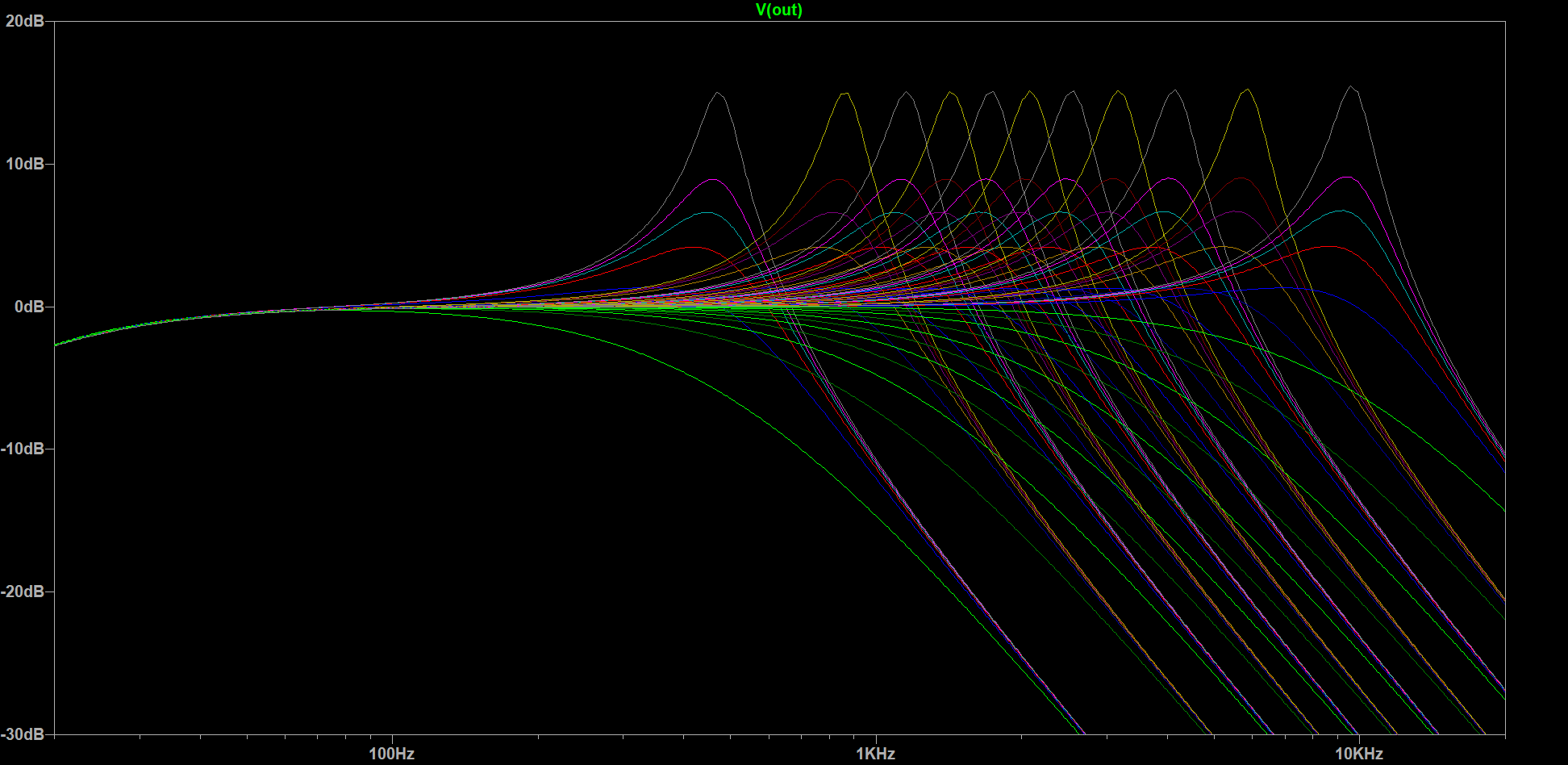
So the simulation agrees with all those calculations, yay! Reality may turn out to be a little more complex, but I need to wait for some parts before I can try it in practice. Additionally, the modified circuit includes some fairly low impedances, which is good for noise performance, but bad for battery life, so I may have to move to higher-value potentiometers as well—which have become rarer as well for some reason. Maybe something in the 200 to 500 kΩ range? Once I have breadboarded everything and decided on component values, I'll either have to convert it to a perfboard layout or try to design a PCB with KiCAD—more expensive but far more compact, especially with SMD components. In any case, that's it for today, and as usual, feel free to follow me and send me a DM on Mastodon if you have any questions or comments.